NEON Visualizer
User's manual
Using the graphical user interface
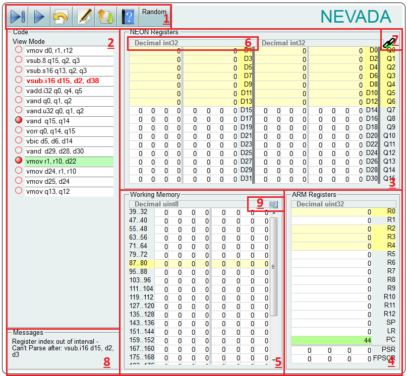
1) Execution controllers

 To next Breakpoint
- Executes from the current point to the end.
 Step
Step- Executes the current instruction.
 Reset
Reset- Sets the Progam Counter to 0.
 Toggle edit/view
- Switches between edit and run mode.
 Load and Save
- Pops up the session management window.
 Help
Help- Displays this page.
- Random
- Pops up a menu for filling the NEON register values with random numbers.
2) Code
View mode
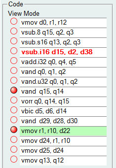
View mode recommended when executing instructions.
Editing insturctions
In this view you can edit the existing instuctions. After editing press enter. If the text changes to red, the instuction is invalid. If you want to add one more instuction, currently you must switch to edit mode.
Toggle breakpoint
At the begining of each line there is a small red circle. (![]() or
or  ) By clicking on them, you can toggle the breakpoint.
The following instruction
A line with light green background indicates the upcoming instruction. You can easily set the upcoming instruction by double clicking on any line.
Edit mode
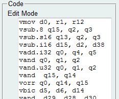
In this mode you can easily edit the instuctions. Currently only in this mode can you add new lines.
3) NEON register set
Here you can see and change the content of the NEON register set.
You can see the current datatype of any register int the Format selector by clicking on it.
Invalid input data highlighted by red. The green values indicates the previously executed instruction's output.
For more information see the Format selector and the Datatype linker.
4) ARM core register set
Here you can see and change the content of the core ARM register set.
Invalid input data highlighted by red. The green values indicates the previously executed instruction's output.
To change the format see Format selector.
5) Memory data
Here you can see and change the content of the memory.
You can see the current datatype of any register in the Format selector by clicking on it.
Invalid input data highlighted by red. The green values indicates the previously executed instruction's output.
To change the format see Format selector.
6) Format selector
Using this menu you can change the selected registers display and input format.
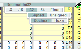
Selecting registers
You can select one register by clicking on it.You can change any number of register's type by selecting multiple lines. Hold shift key when click to select an interval. Hold ctrl key when click to select one more lines.
7) Datatype linker
 ) then when you cahnge the type of any double register, the the other double register's in the quad register also changes. If you see red cross (
 ) then you can change the double register's format individually.
8) Messages
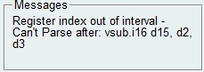 Here you can see informations and error messages. Red flash notifies about new messages.
You usually can get information about an error if you click on it.
9) Memory settings
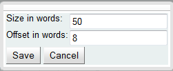
Size
Here you can set the memory size. The input number must be a non negative even number.
Offset
Here you can set the offset of memory. The input number must be a non negative even number.
Loading and saving session
By clicking on the button, a new window pops up.
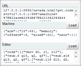
URL
The text contained by the text area is a link with the current state of the machine. The link stores the code, the breakpoints and the values of the registers and memory.
Machine
The text contains the current values of the machine. You can also load register values here by pasting a properly formatted text, and clicking on the Load button above the text area.
Editor
The text contains the current code and the breakpoint. You can also load prevoiusly saved text.
Available instructions
- vand
- vbic
- veor
- vbif
- vbit
- vbsl
- vorr
- vorn
- vmov
- vqmovn
- vqmovun
- vmovn
- vmovl
- vmvn
- vdup
- vld1
- vld2
- vld3
- vld4
- vst1
- vst2
- vst3
- vst4
- vadd
- vaddhn
- vaddl
- vaddw
- vhadd
- vhsub
- vpadal
- vpadd
- vpaddl
- vraddhn
- vrhadd
- vrsubhn
- vqadd
- vqsub
- vsub
- vsubhn
- vsubl
- vsubw
- vqrshl
- vqrshrn
- vqrshrun
- vqshl
- vqshlu
- vqshrn
- vqshrun
- vrshl
- vshl
- vrshr
- vshr
- vrshrn
- vshrn
- vshll
- vrsra
- vsra
- vsli
- vsri
- vacge
- vacgt
- vacle
- vaclt
- vceq
- vcge
- vcgt
- vcle
- vclt
- vtst
- vmla
- vmlal
- vmls
- vmlsl
- vmul
- vmull
- vqdmlal
- vqdmlsl
- vqdmulh
- vqrdmulh
- vqdmull
- vaba
- vabal
- vabd
- vabdl
- vabs
- vqabs
- vcvt
- vcls
- vclz
- vcnt
- vzip
- vuzp
- vtrn
- vtbl
- vtbx
- vswp
- vneg
- vqneg
- vrev16
- vrev32
- vrev64
- vmax
- vmin
- vpmax
- vpmin
- vrecpe
- vrsqrte
- vrecps
- vrsqrts
- vext
- vmrs
- vmsr